

plc basic functions - 15.35
5.A machine ejects parts into three chutes. Three optical sensors (A, B and C) are positioned in each of the slots to count the parts. The count should start when the reset (R) button is pushed. The count will stop, and an indicator light (L) turned on when the average number of parts counted equals 100.
6.Use an FAL instruction to average the values in N7:0 to N7:20 and store them in F8:0.
7.Write and simplify a Boolean equation that implements the masked move (MVM) instruction.
8.a) Write ladder logic to calculate and store the binary sequence in integer memory starting at N7:0 up to N7:200 so that N7:0 = 1, N7:1 = 2, N7:2 = 4, N7:3 = 8, N7:4 = 16, etc. b) Will the program operate as expected?
plc advanced functions - 16.1
16. ADVANCED LADDER LOGIC FUNCTIONS
Topics:
•Shift registers, stacks and sequencers
•Program control; branching, looping, subroutines, temporary ends and one shots
•Interrupts; timed, fault and input driven
•Immediate inputs and outputs
•Block transfer
•Conversion of State diagrams using program subroutines
•Design examples
Objectives:
•To understand shift registers, stacks and sequencers.
•To understand program control statements.
•To understand the use of interrupts.
•To understand the operation of immediate input and output instructions.
•To be prepared to use the block transfer instruction later.
•Be able to apply the advanced function in ladder logic design.
16.1INTRODUCTION
This chapter covers advanced functions, but this definition is somewhat arbitrary. The array functions in the last chapter could be classified as advanced functions. The functions in this section tend to do things that are not oriented to simple data values. The list functions will allow storage and recovery of bits and words. These functions are useful when implementing buffered and queued systems. The program control functions will do things that don’t follow the simple model of ladder logic execution - these functions recognize the program is executed left-to-right top-to-bottom. Finally, the input output functions will be discussed, and how they allow us to work around the normal input and output scans.
16.2LIST FUNCTIONS
16.2.1Shift Registers
Shift registers are oriented to single data bits. A shift register can only hold so many bits, so when a new bit is put in, one must be removed. An example of a shift regis-

plc advanced functions - 16.2
ter is given in Figure 16.1. The shift register is the word B3:1, and it is 5 bits long. When A becomes true the bits all shift right to the least significant bit. When they shift a new bit is needed, and it is taken from I:000/0. The bit that is shifted out, on the right hand side, is moved to the control word UL (unload) bit R6:2/UL. This function will not complete in a single ladder logic scan, so the control word R6:2 is used. The function is edge triggered, so A would have to turn on 5 more times before the bit just loaded from I:000/0 would emerge to the unload bit. When A has a positive edge the bits in B3:1 will be shifted in memory. In this case it is taking the value of bit B3:1/0 and putting it in the control word bit R6:2/UL. It then shifts the bits once to the right, B3:1/0 = B3:1/1 then B3:1/1 = B3:1/2 then B3:1/2 = B3:1/3 then B3:1/3 = B3:1/4. Then the input bit is put into the most significant bit B3:1/4 = I:000/00. The bits in the shift register can also be shifted to the left with the BSL function.
|
|
|
|
|
|
|
|
|
|
|
|
|
|
|
|
|
bits shift right |
|||||
B3:1 |
|
|
|
|
|
|
|
|
|
|
|
|
|
|
|
|
|
|
|
|
||
MSB |
|
|
|
|
|
|
|
|
|
|
|
|
|
|
|
|
|
|
LSB |
|||
0 |
0 |
0 |
0 |
0 |
0 |
0 |
0 |
0 |
0 |
0 |
0 |
0 |
0 |
0 |
0 |
|||||||
|
|
|
15 |
|
|
|
|
|
|
|
|
|
|
|
|
|
|
|
|
|
|
00 |
|
|
|
|
|
|
|
|
|
|
|
|
|
|
|
|
|
|
|
|
|
||
|
|
|
|
|
|
|
|
|
|
I:000/00 |
|
|
|
|
R6:2/UL |
|||||||
|
|
|
|
|
|
|
|
|
|
|
|
|
|
|
||||||||
|
|
|
|
|
|
|
|
|
|
5 |
|
|
|
|||||||||
|
|
A |
|
|
|
|
|
|
|
|
|
|
|
|
|
|
|
|
|
|
|
|
|
|
|
|
|
|
|
|
|
|
|
|
|
|
|
|
BSR |
|
|
|
|
||
|
|
|
|
|
|
|
|
|
|
|
|
|
|
|
|
|
File B3:1 |
|||||
|
|
|
|
|
|
|
|
|
|
|
|
|
|
|
|
|
||||||
|
|
|
|
|
|
|
|
|
|
|
|
|
|
|
|
|
Control R6:2 |
|||||
|
|
|
|
|
|
|
|
|
|
|
|
|
|
|
|
|
Bit address I:000/00 |
|||||
|
|
|
|
|
|
|
|
|
|
|
|
|
|
|
|
|
Length 5 |
|||||
|
|
|
|
|
|
|
|
|
|
|
|
|
|
|
|
|
|
|
|
|
|
|
BSL - shifts left from the LSB to the MSB. The LSB must be supplied
BSR - similar to the BSL, except the bit is input to the MSB and shifted to the LSB
Figure 16.1 Shift Register Functions
There are other types of shift registers not implemented in PLC-5s. These are shown in Figure 16.2. The primary difference is that the arithmetic shifts will put a zero into the shift register, instead of allowing an arbitrary bit. The rotate functions shift bits around in an endless circle. These functions can also be implemented using the BSR and BSL instructions when needed.
plc advanced functions - 16.3
Arithmetic Shift Left (ASL) |
|
|
|
|
|
|
|
|
|
|
|
|
|
||||
|
carry |
msb |
|
|
|
|
|
|
|
|
lsb |
|
|
|
|||
|
0 |
|
0 |
|
0 |
0 |
0 |
0 |
0 |
0 |
0 |
|
0 |
|
|
||
|
|
|
|
|
|
|
|||||||||||
Arithmetic Shift Right (ASR) |
|
|
|
|
|
|
|
|
|
|
|
carry |
|||||
0 |
|
|
|
|
|
|
|
|
|
|
|
|
|
||||
0 |
|
0 |
0 |
0 |
0 |
0 |
0 |
0 |
|
||||||||
|
|
|
0 |
|
|||||||||||||
Rotate Left (ROL) |
|
|
|
|
|
|
|
|
|
|
|
|
|
|
|||
|
|
|
|
|
|
|
|
|
|
|
|
|
|
|
|||
0 |
|
0 |
0 |
0 |
0 |
0 |
0 |
0 |
|
|
|
|
|||||
|
|
|
|
|
|
|
|
||||||||||
|
|
|
|
|
|
|
|
carry |
|
|
|
|
|
|
|
||
|
|
|
|
|
|
|
|
|
0 |
|
|
|
|
|
|
|
|
Rotate Right (ROR) |
|
|
|
|
|
|
|
|
|
|
|
|
|
|
|
||
0 |
|
0 |
0 |
0 |
0 |
0 |
0 |
0 |
|
|
|
|
|||||
|
|
|
|
|
|
|
|
||||||||||
carry 
 0
0 
Figure 16.2 Shift Register Variations
16.2.2 Stacks
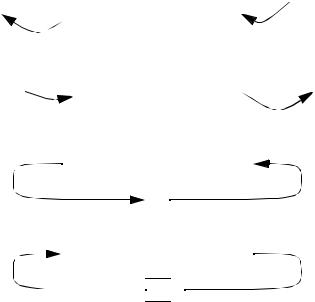
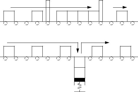
Stacks store integer words in a two ended buffer. There are two basic types of stacks; first-on-first-out (FIFO) and last-in-first-out (LIFO). As words are pushed on the stack it gets larger, when words are pulled off it gets smaller. When you retrieve a word from a LIFO stack you get the word that is the entry end of the stack. But, when you get a word from a FIFO stack you get the word from the exit end of the stack (it has also been there the longest). A useful analogy is a pile of work on your desk. As new work arrives you drop it on the top of the stack. If your stack is LIFO, you pick your next job from the top of the pile. If your stack is FIFO, you pick your work from the bottom of the pile. Stacks are very helpful when dealing with practical situations such as buffers in production lines. If the buffer is only a delay then a FIFO stack will keep the data in order. If product is buffered by piling it up then a LIFO stack works better, as shown in Figure 16.3. In a FIFO stack the parts pass through an entry gate, but are stopped by the exit gate. In the LIFO stack the parts enter the stack and lower the plate, when more parts are needed the plate is raised. In this arrangement the order of the parts in the stack will be reversed.
plc advanced functions - 16.4
entry gate |
exit gate |
FIFO |
|
LIFO
Figure 16.3 Buffers and Stack Types
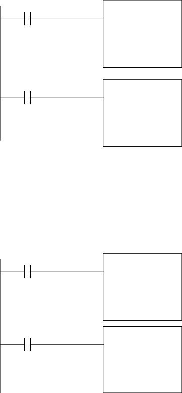
The ladder logic functions are FFL to load the stack, and FFU to unload it. The example in Figure 16.4 shows two instructions to load and unload a FIFO stack. The first time this FFL is activated (edge triggered) it will grab the word (16 bits) from the input card I:001 and store them on the stack, at N7:0. The next value would be stored at N7:1, and so on until the stack length is reached at N7:4. When the FFU is activated the word at N7:0 will be moved to the output card O:003. The values on the stack will be shifted up so that the value previously in N7:1 moves to N7:0, N7:2 moves to N7:1, etc. If the stack is full or empty, an a load or unload occurs the error bit will be set R6:0/ER.
plc advanced functions - 16.5
A
FFL
source I:001 FIFO N7:0 Control R6:0 length 5 position 0
B
FFU
FIFO N7:0 destination O:003 Control R6:0 length 5
position 0
Figure 16.4 FIFO Stack Instructions
The LIFO stack commands are shown in Figure 16.5. As values are loaded on the stack the will be added sequentially N7:0, N7:1, N7:2, N7:3 then N7:4. When values are unloaded they will be taken from the last loaded position, so if the stack is full the value of N7:4 will be removed first.
A
LFL
source I:001 LIFO N7:0 Control R6:0 length 5 position 0
B
LFU
LIFO N7:0 destination O:003 Control R6:0 length 5
position 0
Figure 16.5 LIFO Stack Commands